RY Strain Gauge Rosettes with 3 Measuring Grids for Analyzing Biaxial Stress States with Unknown Principal Directions
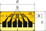
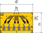
RY strain gauges have 3 measuring grids arranged at an angle of 0°/45°/90° (types RY1, RY3, RY8, RY9, RY10), or 0°/60°/120° (types RY4, RY7). These strain gauges (SGs) are an appropriate choice for analyzing the biaxial stress state with unknown principal directions.
With these types we offer you strain gauges (SG) in various geometries and sizes, each available with temperature responses adapted to the following materials:
- Ferritic steel (10.8 ppm/K; 6.0 ppm/°F); temperature matching code: 1
- Aluminum (23 ppm/K; 12.8 ppm/°F); temperature matching code: 3
- Austenitic steel (16 ppm/K, 8.9 ppm/°F); temperature matching code: 5
- Silica/composite (0,5 ppm/K; 0.3 ppm/°F); temperature matching code: 6
- Titanium and gray cast iron (9 ppm/K; 5.0 ppm/°F); temperature matching code: 7
- Plastic (65 ppm/K; 36.1 ppm/°F); temperature matching code: 8
- Molybdenum (5.4 ppm/K; 3.0 ppm/°F); temperature matching code: 9
Insert the temperature matching code in place of the placeholder “x” to get the ordering number of the strain gauge you need. Strain gauges marked with a # symbol are only available matched to aluminum, ferritic and austenitic steel.
Save time and efforts: RY8 strain gauges are available as pre-wired versions with connection cable
Measuring grid consists of constantan, measuring grid carrier is polymide
Fast delivery for preferred strain gauge types - available from stock!
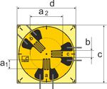 | Ordering number | Nominal (rated) resistance | Dimensions [mm/inch] | Solder terminals | Preferred types | ||||||||||
Measuring grid | Carrier | ||||||||||||||
[Ω] | a1 | a2 | b | c | d | ||||||||||
1-RY1x-3/120# | 120 | 0.8 | 3 | 0.8 0.031 | 7 0.276 | 7 0.276 | LS7 | 1 | |||||||
| Steel (1) | Aluminum (3) | Austenitic Steel (5) | Silica / composite (6) | Titanium (7) | Plastic (8) | Molybdenum (9) | |||||||||||||||
| 1-RY1x-6/120 | 120 | 2 | 6 | 1.4 0.055 | 11 0.433 | 11 0.433 | LS5 | 1,3 | |||||||
| Steel (1) | Aluminum (3) | Austenitic Steel (5) | Silica / composite (6) | Titanium (7) | Plastic (8) | Molybdenum (9) | |||||||||||||||
1-RY1x-10/120 | 120 | 2.9 | 10 | 2.7 0.106 | 15.4 0.606 | 15.4 0.606 | LS4 | 1 | |||||||
| Steel (1) | Aluminum (3) | Austenitic Steel (5) | Silica / composite (6) | Titanium (7) | Plastic (8) | Molybdenum (9) | |||||||||||||||
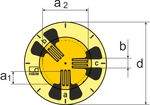 | Ordering number | Nominal (rated) resistance | Dimensions [mm/inch] | Solder terminals are not compulsory | Preferred types | |||
Measuring grid | Carrier | |||||||
[Ω] | a1 | a2 | b | d | ||||
1-RY3x-3/120# | 120 | 0.8 | 3 | 0.8 | 6.9 | LS7 | 1 | |
| Steel (1) | Aluminum (3) | Austenitic Steel (5) | Silica / composite (6) | Titanium (7) | Plastic (8) | Molybdenum (9) | ||||||||
1-RY3x-6/120 | 120 | 2 | 6 | 1.4 | 11 | LS5 | 1,3 | |
| Steel (1) | Aluminum (3) | Austenitic Steel (5) | Silica / composite (6) | Titanium (7) | Plastic (8) | Molybdenum (9) | ||||||||
1-RY3x-10/120 | 120 | 2.9 | 10 | 2.7 | 15.4 | LS4 | 1 | |
| Steel (1) | Aluminum (3) | Austenitic Steel (5) | Silica / composite (6) | Titanium (7) | Plastic (8) | Molybdenum (9) | ||||||||
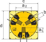 | Ordering number | Nominal (rated) resistance | Dimensions [mm/inch] | Solder terminals
| Preferred types | ||||||||||
Measuring grid | Carrier | ||||||||||||||
[Ω] | a1 | a2 | b | c | d | ||||||||||
1-RY4x-3/120# | 120 | 0.8 | 3 | 0.8 0.031 | 7 0.276 | 7 0.276 | LS7 | - | |||||||
| Steel (1) | Aluminum (3) | Austenitic Steel (5) | Silica / composite (6) | Titanium (7) | Plastic (8) | Molybdenum (9) | |||||||||||||||
1-RY4x-6/120 | 120 | 2 | 6 | 1.4 0.055 | 11 0.433 | 11 0.433 | LS5 | 1 | |||||||
| Steel (1) | Aluminum (3) | Austenitic Steel (5) | Silica / composite (6) | Titanium (7) | Plastic (8) | Molybdenum (9) | |||||||||||||||
1-RY4x-10/120 | 120 | 2.9 | 10 | 2.7 0.106 | 15.4 0.606 | 15.4 0.606 | LS4 | 1 | |||||||
| Steel (1) | Aluminum (3) | Austenitic Steel (5) | Silica / composite (6) | Titanium (7) | Plastic (8) | Molybdenum (9) | |||||||||||||||
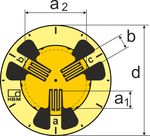 | Ordering number | Nominal (rated) resistance | Dimensions [mm/inch] | Solder terminals are not compulsory | Preferred types | |||
Measuring grid | Carrier | |||||||
[Ω] | a1 | a2 | b | d | ||||
1-RY7x-3/120# | 120 | 0.8 | 3 | 0.8 0.031 | 6.9 0.272 | LS7 | - | |
| Steel (1) | Aluminum (3) | Austenitic Steel (5) | Silica / composite (6) | Titanium (7) | Plastic (8) | Molybdenum (9) | ||||||||
1-RY7x-6/120 | 120 | 2 | 6 | 1.4 0.055 | 11 0.433 | LS5 | - | |
| Steel (1) | Aluminum (3) | Austenitic Steel (5) | Silica / composite (6) | Titanium (7) | Plastic (8) | Molybdenum (9) | ||||||||
1-RY7x-10/120 | 120 | 2.9 | 10 | 2.7 0.106 | 15.5 | LS4 | - | |
| Steel (1) | Aluminum (3) | Austenitic Steel (5) | Silica / composite (6) | Titanium (7) | Plastic (8) | Molybdenum (9) | ||||||||
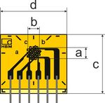
 | Ordering number | Nominal (rated) resistance | Dimensions [mm/inch] | Solder terminals are not compulsory
| Preferred types | |||
Measuring grid | Carrier | |||||||
[Ω] | a | b | c | d | ||||
1-RY8x-0.6/120# | 120 | 0.6 | 1.1 0.043 | 4.8 0.189 | 8.7 0.343 | LS7 | - | |
| Steel (1) | Aluminum (3) | Austenitic Steel (5) | Silica / composite (6) | Titanium (7) | Plastic (8) | Molybdenum (9) | ||||||||
1-RY8x-1.5/120 | 120 | 1.5 | 1.2 0.047 | 8.2 0.323 | 14.6 0.575 | LS7 | 1 | |
| Steel (1) | Aluminum (3) | Austenitic Steel (5) | Silica / composite (6) | Titanium (7) | Plastic (8) | Molybdenum (9) | ||||||||
1-RY8x-3/120 | 120 | 3 | 1.1 0.043 | 9.7 0.382 | 14.6 0.575 | LS7 | 1,3 | |
| Steel (1) | Aluminum (3) | Austenitic Steel (5) | Silica / composite (6) | Titanium (7) | Plastic (8) | Molybdenum (9) | ||||||||
1-RY8x-6/120 | 120 | 6 | 3 0.118 | 13 0.512 | 22.9 0.902 | LS7 | 1 | |
| Steel (1) | Aluminum (3) | Austenitic Steel (5) | Silica / composite (6) | Titanium (7) | Plastic (8) | Molybdenum (9) | ||||||||
1-RY8x-1.5/350# | 350 | 1.5 | 1.6 0.063 | 8.2 0.323 | 14.6 0.575 | LS7 | - | |
| Steel (1) | Aluminum (3) | Austenitic Steel (5) | Silica / composite (6) | Titanium (7) | Plastic (8) | Molybdenum (9) | ||||||||
1-RY8x-3/350 | 350 | 3 | 1.2 0.047 | 9.7 0.382 | 14.6 0.575 | LS7 | - | |
| Steel (1) | Aluminum (3) | Austenitic Steel (5) | Silica / composite (6) | Titanium (7) | Plastic (8) | Molybdenum (9) | ||||||||
1-RY8x-6/350 | 350 | 6 | 2.8 0.11 | 13.1 0.516 | 22.9 0.902 | LS5 | 1 | |
| Steel (1) | Aluminum (3) | Austenitic Steel (5) | Silica / composite (6) | Titanium (7) | Plastic (8) | Molybdenum (9) | ||||||||
 | Ordering number | Nominal (rated) resistance | Dimensions [mm/inch] | Solder terminals
| Preferred types | |||
Measuring grid | Carrier | |||||||
[Ω] | a | b | c | d | ||||
1-RY10x-1.5/120 | 120 | 1.5 | 1.4 0.055 | 8.2 0.323 | 13.5 0.531 | LS7 | - | |
| Steel (1) | Aluminum (3) | Austenitic Steel (5) | Silica / composite (6) | Titanium (7) | Plastic (8) | Molybdenum (9) | ||||||||
1-RY10x-3/120 | 120 | 3 | 1.1 0.043 | 9.7 0.382 | 13.5 0.531 | LS7 | 1, 3 | |
| Steel (1) | Aluminum (3) | Austenitic Steel (5) | Silica / composite (6) | Titanium (7) | Plastic (8) | Molybdenum (9) | ||||||||
1-RY10x-6/120 | 120 | 6 | 3 0.118 | 16.4 0.646 | 22.9 0.902 | LS4 | - | |
| Steel (1) | Aluminum (3) | Austenitic Steel (5) | Silica / composite (6) | Titanium (7) | Plastic (8) | Molybdenum (9) | ||||||||
| 1-RY10x-1.5/350# | 350 | 1.5 | 1.4 0.055 | 8.2 0.3232 | 13.5 0.531 | LS7 | 1,3 | |
| Steel (1) | Aluminum (3) | Austenitic Steel (5) | Silica / composite (6) | Titanium (7) | Plastic (8) | Molybdenum (9) | ||||||||
1-RY10x-3/350 | 350 | 3 | 1.2 0.047 | 9.7 0.382 | 13.5 0.531 | LS7 | 1,3 | |
| Steel (1) | Aluminum (3) | Austenitic Steel (5) | Silica / composite (6) | Titanium (7) | Plastic (8) | Molybdenum (9) | ||||||||
1-RY10x-6/350 | 350 | 6 | 2.8 0.11 | 16.4 0.646 | 22.9 0.902 | LS4 | 1,3,6 | |
| Steel (1) | Aluminum (3) | Austenitic Steel (5) | Silica / composite (6) | Titanium (7) | Plastic (8) | Molybdenum (9) | ||||||||
The measuring grid consists of constantan; the material of the measuring grid carrier is polyimide.
RY6/RY8 strain gauges also come with a connection cable! One practical solution with many advantages: No soldering required at the measuring point, available in cable lengths from 0.5 m to 10 m, with RJ11 plug on request. A fluoropolymer-insulated wire on the strain gauge prevents the cable from sticking during installation. A practical solution for you...!
간소화된 문서화 및 파라미터화
측정점 문서화를 최적화하기 위해 각 스트레인 게이지에는 측정 지점 옆과 측정 앰프 근처에 부착할 수 있는 두 개의 스티커가 포함되어 있습니다. 측정 설정에서 직접 파라미터 정보를 활용할 수 있습니다.
- 각 스트레인 게이지의 데이터 시트 에 직접 연결되는 QR 코드
- 제품 및 생산 배치 번호
- k 팩터 와 메모를 위한 추가 공간
- 스캐너로 컴퓨터 보조 파라미터화 또는 문서화를 단순화하기 위해 개별 스트레인 게이지의 값 을 포함하는 QR 코드
참고: 새로 생산된 스트레인 게이지는 모두 스티커와 함께 제공되며, 기존 재고 스트레인 게이지에는 이 기능이 포함되지 않습니다.
Product Literature
| 제목 / 설명 | 언어 | 제품 | 언어 | 종류 |
|---|---|---|---|---|
| 데이터 시트 | ||||
| Dehnungsmessstreifen - Katalog | German | |||
| Strain Gauges - Catalogue | English | |||
| Тензорезисторы - катало́г | Russian | |||
| Declaration of Conformity | ||||
| Strain Gauges and Accessories - Statement of Compliance | English | |||
| Tech Notes | ||||
| Determine the thermal expansion coefficient | English | |||
| Wärmeausdehnungskoeffizient bestimmen | German | |||