Selecting a suitable force-torque sensor often seems simple at first glance – what is going to be measured and what is the approximate measurement range? Once you have found answers to these two questions, there are a few more aspects that need to be considered. The next step is to think about the transducer’s load limits. In the following white paper, we will take a closer look at what to bear in mind when considering the permissible loads, what special aspects to consider, and how to make a sensible assessment.
Step by Step: Load Analysis for Force-Torque Sensors
Data Sheet Specifications and Their Relationships
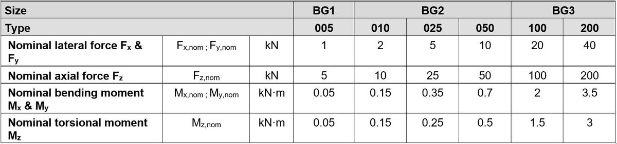
When looking at the data sheet of a multiaxial force/torque sensor, for example, the data sheet of the HBK MCS10, you will find detailed information about maximum permissible forces, moments, or criteria to be observed (see Figure 1 and Figure 2). The data may vary depending on the manufacturer or type. However, it always is a quality criterion that plays a decisive role in finding the most suitable multi axis sensor for the application.
When taking a closer look at these specifications, you will find some related terms that need to be explained:
- Nominal force/Nominal moment
- Force limit/Moment limit
- Force at break/Moment at break
- Load ratio sum (LRS)
- Criterion to be met at multiaxial load for…
- Nominal (rated) measurement range
- Fatigue strength range
- At pulsating load
- At alternating load
- Static load range
- Range without break
The best way to understand how the individual terms are related is to consider which load types can occur and how they can be classified. Scroll down for an interactive guide that links the load types and the associated limits or criteria and tells you if your sensor can carry its load under the given cirumstances. In selected applications, other loads, for example, due to temperature or other environmental influences, should be considered in addition to the mechanical loads shown here. In most cases, however, this is not necessary or, in case of doubt, can be easily and quickly clarified.
However, regardless of whether we are talking about uniaxial or multiaxial, static or dynamic, pulsating or alternating, there are test criteria that should be applied to ensure the safe operation of the sensor.
Interactive Guide
Use this interactive guide together with the given limits and criterions in the datasheet to find out if your sensor can carry the loads. Simply select the applicable options.
Download
To download the interactive guide as a printable flow chart, click here.
Uniaxial vs Multiaxial Load
Uniaxial loading means that the sensor is subjected to loads in one direction of the coordinate system or around one axis only. As soon as a further load is added, whether it be a force or a moment, this is referred to as multiaxial loading. Up to six loads can occur simultaneously: three forces Fx, Fy, Fz and three moments Mx, My, Mz.
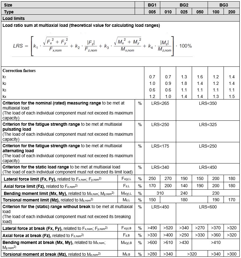
In general, a load applied from the outside results in mechanical stress in the sensor’s measuring body. In the case of multiaxial loads, the objective is to combine them so that they can be compared to a single test criterion. Here, this is done by calculating the load ratio sum (LRS):
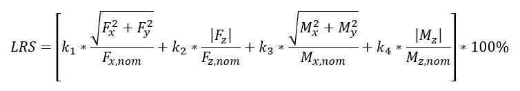
This formula includes all existing loads, the permissible maximum capacities and the four correction factors. These can also be found in the MCS10 data sheet (see Figure 2).
Static vs Dynamic and Pulsating vs Alternating Load
Static loading means that the sensor is subjected to a load that does not change over time, that is, it is constant and not variable. Dynamic loading, on the other hand, means that the load varies over time, that is, it is not constant. In many applications, static loads involve the process of applying and removing the load. Up to the point of reaching the static load, the load increases dynamically and decreases dynamically again when the load is removed. Often these applications can be considered purely static, but in case of doubt, it can also be useful to consider the application and removal of the load as individual dynamic load cases.
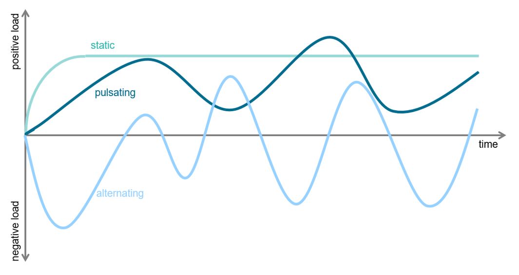
Dynamic loading further distinguishes between pulsating and alternating loading. The decisive factor here is that with pulsating loading no reversal of the load direction takes place. This means that the compressive or tensile force applied to the sensor or the torsion in one direction around an axis only varies in so far as it is stronger at times and weaker at other times. Alternating loading, on the other hand, means that tensile and compressive forces or clockwise and counterclockwise torque alternate. This is also illustrated by a sign reversal of the loads.
Figure 4 shows an example of the time histories due to applied loads for these three cases. The test criterion for alternating loads is the most stringent, as they put the greatest load on the transducer.
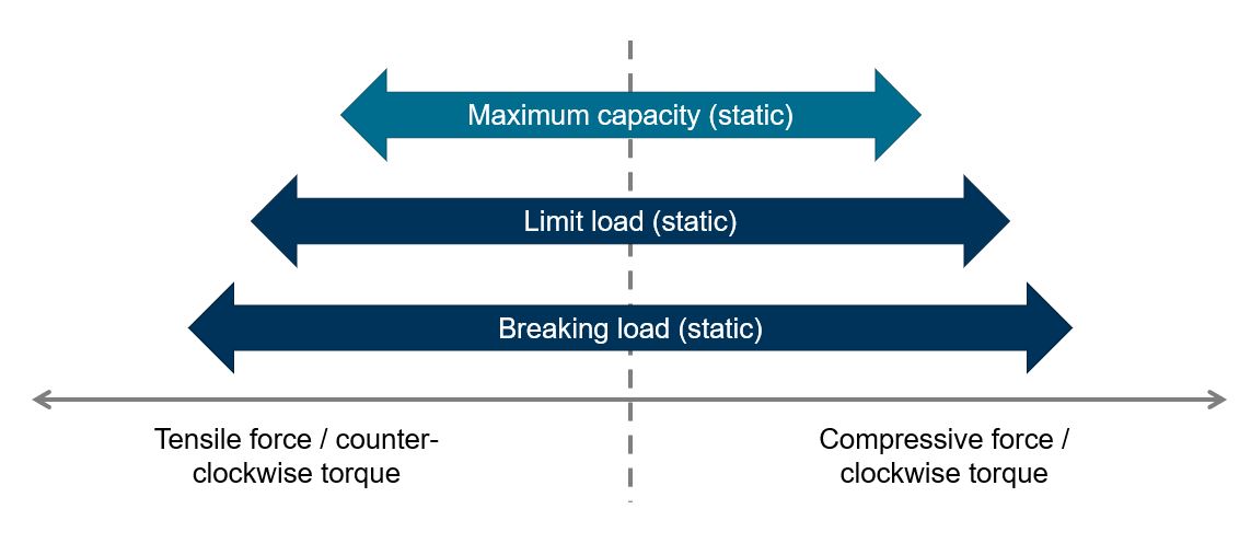
Maximum Capacity, Limit Load, Breaking Load
The differentiation between these three load limits is not particularly difficult; however, it is essential to ensure the safe use of a sensor. The technical specifications of the sensor are guaranteed up to its maximum capacity. For loads exceeding the maximum capacity and ranging up to the limit load, the specifications can no longer be guaranteed. However, loads in this range are still permissible and do not damage the sensor if they do not occur too frequently. When further increasing the load to the range between the limit load and the breaking load, the measuring body is deformed to such an extent that it is permanently damaged and the sensor can no longer be used for further measurements. Loads exceeding the breaking load limit will lead to a breakage of the sensor. It is important to note that these load ranges only apply to the uniaxial and static load cases.
Special Aspects and Possible Omissions
A potentially trivial but occasionally neglected aspect is that a sensor must withstand loads in all six directions, even if they are not measured. If, for example, a three-channel force sensor (Fx, Fy, Fz) is used, it must of course also withstand moments that occur – even if they are not measured. It does not matter whether these moments are directly introduced as torque, or whether they result from an applied force and the lever arm from the force application point to the coordinate origin.
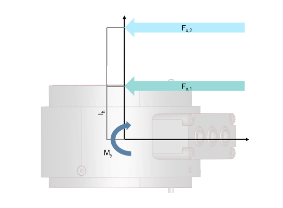
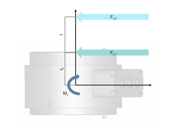
The latter leads to another particularity: with the MCS10, the position of the coordinate origin is in the centre of the measuring body. If a force Fx,1 is applied directly at the measuring body surface, this results in the lever arm lh (half the height of the sensor) and the moment My. If the force is introduced further away from the sensor, for example, due to the test setup, the lever arm is lh + l and, together with force Fx,2, results in a larger moment, My. For this reason, the forces should always be applied as close as possible to the sensor and, if the levers are longer, a closer look should be taken.
Practical Application
Now that the different types of loads, limits, and criteria have been examined, the question arises as to how best to estimate the loading of a transducer in an application. The following procedure has proved practicable:
- Selection according to maximum capacities
- Determination of all maximum loads
- Definition of load cases
- Consideration of the individual load cases
- Overall assessment
Selection according to maximum capacities
In most cases, the directions to be measured are known and the maximum capacities can be estimated as absolute values. This knowledge can be used to select a sensor.
Determination of all loads occurring
The maximum loads for each load direction can be derived from the maximum loads occurring in the application as well as the geometric arrangement (torque = force x lever arm). It makes sense to take note of these not only as an absolute value but with a sign. This task is often time-consuming, especially with more complex setups and interacting forces. However, it is the basis for a reliable assessment and therefore necessary.
In addition to the maximum loads, further loads may also be relevant. Especially when a different type of load is involved. For example, if the maximum load is static, but a slightly lower load is alternating and dynamic, both cases must be investigated.
Definition of load cases
Often, not all loads occur at the same time. There may be a regular mode of operation with two forces and one moment, as well as a mode at the start and stop of the application with a different force. To be able to consider these situations separately, it makes sense to subdivide them into separate load cases and study each load case individually. It is advisable to create a table overview here.
Consideration of the individual load cases
The interactive guide on this page helps to find the correct limit value or the correct criterion for examining the individual load cases in this step. For each load case, the actual load is compared with the limit and evaluated, or the LRS calculated for this case is compared with the respective criterion and evaluated. To avoid having to calculate the LRS manually every time, a template for Microsoft® Excel® can be downloaded here. This enables you to automate this step.
Overall assessment
Having carried out the steps described above, you will obtain a table, ideally with only positive results of the individual load cases. In this table, it makes sense not only to note OK or not OK but to also note the exact result. This makes it easy to see whether a sensor that is not suitable for the measurement range has been selected or whether all results are coherent.
Conclusions
Selecting and assessing a multi-component sensor is not trivial. However, if you follow this step-by-step process and prepare a flow chart, the topic can be easily handled and you will obtain a reliable statement as a result.