
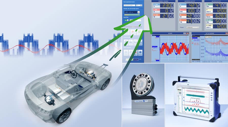
Drive hybridization means that requirements for test bench test and measuring equipment have become considerably more stringent. And if these requirements are to be satisfied by measurement systems for different tasks, the complexity of the test bench increases dramatically – to the chagrin of test bench constructors and users. The eDrive solution from HBM offers turnkey test and measuring equipment for even the most complex test benches, all from a single source, including the real-time transfer of data to the automation system.
Everything from a single source with real-time data transfer
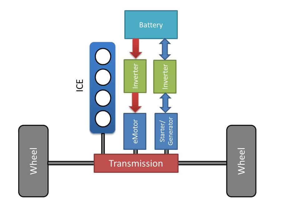
For many years, drive test benches in automotive engineering always had a very similar design. After all, the object under test was always the same: a combustion engine, and possibly a transmission. Therefore, the test and measuring equipment used was also extremely similar. Over time, standards came into being and proved their worth. At the end of the day, the focus was mostly on optimizing test routines, shortening test times and therefore cutting costs. Technical modifications were brought about by the increasing number of bus systems in test specimens, and the introduction of real-time fieldbuses for automation.
Familiar slow signals such as temperature, pressure, vibration – but now insulated
The first group of measurement signals are rather slow variables such as pressure, vibration and temperature. As a rule, these are used to determine the "general status" of the test bench and test specimen, to ensure the correct conditions for actual testing. However, things are now rendered more difficult by the need to insulate these inputs – sometimes up to 1000 V – for technical or safety reasons. If the temperature is measured directly at an inverter of the auxiliary drive, for example, it would be advisable from a technical safety perspective to insulate these temperature channels. This protects the measuring equipment and the operators in the event of a malfunction in the inverter. Even if the winding temperature of the motor also needs to be measured on a development test bench, the sensor must be insulated, just as when measuring the temperature on the HV battery.
Mechanical power variables such as torque, angle of rotation and rotational speed – but now dynamic
After the fundamental mechanical variables, mechanical power variables now come into play, with rotational speed and torque the first in line. Here, too, hybrid test benches face more exacting requirements. For example, the rotational speed of an electric motor can be much higher, and torque fluctuations can also lie in a higher frequency range. This is due to the number of pole pairs of the motor which, together with the magnets, is responsible not just for the rotational motion but also for the torque ripple. This is an interfering signal that must be recorded in order to understand its effects on the test specimen, the test bench and, of course, the drive train itself. Here, measurement needs to be more dynamic than on a pure combustion engine test bench, on which so-called torque peaks are only generated by the combustion process, which is of a much lower frequency than the torque ripple. Things also get more complicated when the mechanical power needs to be measured several times – if the power produced by the combustion engine and the electric motor have to be analyzed separately, for example. Then, two measurement flanges and two rotational speed measuring systems have to be used.
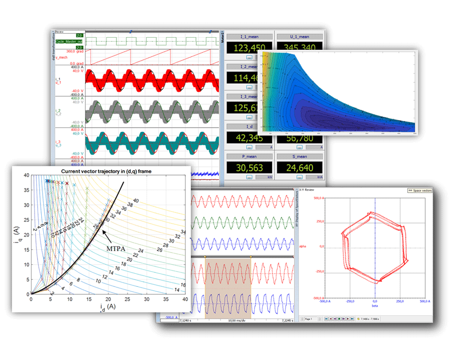
Measurement of the angle of rotation is another special case. If the signals of the electric motor are to be analyzed later on, e.g. in order to produce flux maps or MTPA (maximum torque per ampere, Figure 3) curves, the position of the rotor is crucial for the necessary mathematical analysis.
Electrical power values and efficiency – the greatest challenge
Now we are entering a completely new field: that of electrical power measurements. Power analyzers are normally used for this purpose, but they present the test bench of a dynamic motor with an array of problems. Conventional power analyzers are optimized for use in the network, or with "white goods". The measurement cycles are suitably slow, so that greater accuracies can be achieved through averaging. However, it is precisely these slow data rates that stand in the way of dynamic measurement, or rapid progress through a characteristic map with thousands of measurement points. And in most cases, there is no connection to a fieldbus system.
Yet another problem is the restriction of the number of channels to three or four power channels in most cases. What may just about suffice for three-phase motors and an intermediate circuit becomes a problem when there are five or six-phase motors or other complex systems.
Still, one of the most frequently underestimated problems is that of complete traceability. Power analyzers deliver ready calculated results, and are unable to store raw data. Therefore, comprehensive tracing of the measurement chain is not possible. Calibrated power analyzers may indeed be used, but they are normally calibrated with pure sinusoidal signals at 53 Hz. But in the hybrid drive, PWM signals in the range of several kHz have to be measured. A calibration certificate is unable to demonstrate exactly how a power analyzer can perform measurements in such cases. In the aftermath of #dieselgate, this problem is obviously going to require even more attention in future.
Another often underappreciated detail is the synchronicity required for an efficiency measurement. If we intend to compare the electrical power input with the mechanical power output – i.e. calculate efficiency – these power values need to have been obtained and averaged in precisely the same measurement window. For dynamic measurements, even the most disparate sample rates and input filters influence the electrical and mechanical signals, and may play a considerable part in possible measurement errors.
Raw data as a remedy
The storage of raw data provides an escape from the problem of traceability. Here, in addition to the measured values for power, small extracts of raw data – i.e. current and voltage – are stored at a higher resolution. This permits the subsequent, renewed calculation of power values such as active and reactive power and the mechanical power values, enabling the calculated efficiency map to be verified. This verifiability extends back to the raw data and the sensors, not just to the power analyzers. Of course, power analyzers can also store raw data, but they have not been optimized for this task. The recording and storage of a single setpoint just a few millimeters long can easily take 10 or 20 s. Consequently, the test sequence for measuring the characteristic map is drastically lengthened because of the power analyzer's lack of real-time storage capability.
Raw data storage, power calculation and transfer of results – all in real time
In order to overcome all the problems outlined above, there is a need for new approaches that extend beyond conventional combinations of test bench test and measuring equipment and power analyzers. The challenge of accomplishing as many of the above-mentioned tasks as possible with just one system can be hugely simplified with a hybrid test bench, in terms of both test and measuring equipment and communication with the automation system.
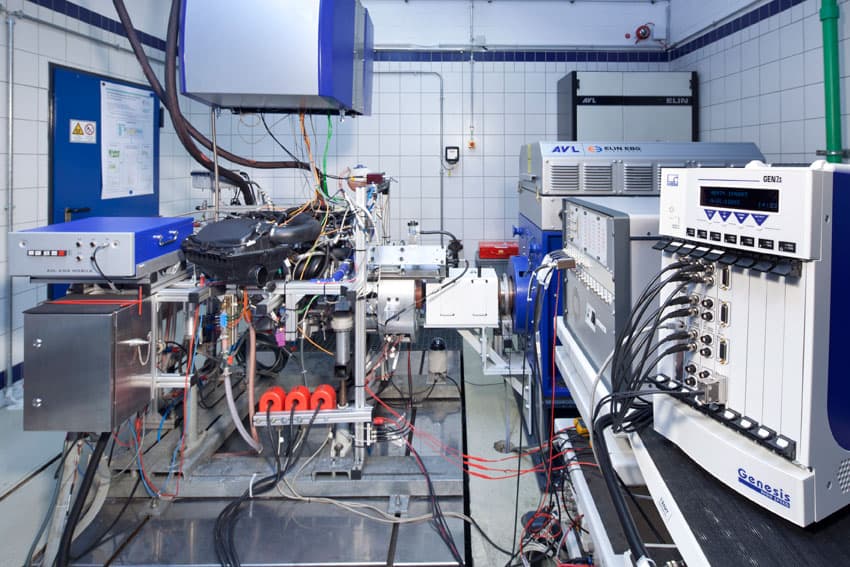
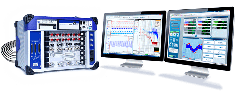
Such an approach is offered by the eDrive GEN DAQ measurement system from HBM (Figure 4).
This appropriately configured modular device records all the necessary signals synchronously and simultaneously. Plug-in cards for current and voltage signals, mechanical variables such as vibration or pressure, and special satellites for recording bus signals and, as a special feature, temperatures with thermocouples with insulated inputs up to 1,000 V.
With the mainframe, the rotational speed, torque and angle signal can be recorded directly and simultaneously for up to six measuring points.
The plug-in cards feature digital signal processors, which record the incoming signals, ascertain the fundamentals of the currents, and calculate the usual power parameters such as active power, reactive power, lambda and similar in real time per half cycle. Controlled by the automation, the trigger function enables any amount of raw data to be stored per setpoint, also in real time. Storage takes place on a hard disk integrated in the mainframe, so as not to overburden the automation system with these extremely high data rates in the megasample range (Figure 5).
Since temperatures and CAN bus signals are also recorded, it is now possible to compensate temperatures (balance the winding resistance based on the measured temperature), for example. Furthermore, step-function responses of the control due to rapid torque steps, triggered by a bus command, can be analyzed with ease.
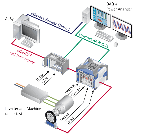
The complete measurement system is controlled from a Windows computer, although the interior of the mainframe houses a real-time version of the LINUX operating system. Therefore, it is now possible to forward the computer results in real time, at the same time as raw data are stored. For this the EtherCAT bus – virtually standard in the automotive industry – is used. Results are calculated up to 1000 times a second, and forwarded to the automation system with a maximum latency of 1 ms. Since more in-depth analyses can simultaneously be performed in real time, a whole range of new possibilities can be achieved in control. Instead of traditional torque control, the test bench can be set to the maximum q current (calculated in real time using Park's transformation), minimizing losses in the drive.
Easily expandable for four-wheel drive test benches or eCVTs
The final advantage of the measurement equipment concept described above is its upward expandability. This allows it not only to be adapted to different types of input signal, but also enables practically unlimited additional channels. Then, the use of further measurement cards permits measurement tasks of even greater complexity to be accomplished. If a six-phase motor needs to be measured, we no longer require two power analyzers, but merely one more plug-in card. And a complex application such as an eCVT with a combustion engine, two electric motors and four torque shafts can also be successfully handled with a single system.

About the author
Dipl. Ing. Klaus Lang is the Business Development Manager for eDrive (= test systems for inverter-fed electrical machines) at HBM in Darmstadt.
Conclusion: Enormous simplification for hybrid test benches
The eDrive test system from HBM entails huge benefits for system integrators, where the simplification of measurement strategies is concerned. Instead of several measurement systems for different signals and with high numbers of channels, just one system is needed. And thanks to the connection to the EtherCAT real-time bus system – so far unique in this field – the data streams are integrated in existing structures with the greatest of ease.
For the user, the optional raw data storage, in particular, offers enormous advantages, as do traceability to raw data and extended analyses such as the determination of d,q currents and MTPA maps.